Hello…are there anybody out there in the whole world wide web? Well, I don’t blame you. The last time I’ve posted anything was many moons ago, but I won’t bore you with all the mundane things that I’ve been doing. There is one more challenge I’d like to take on and it does take quite a bit of time to resolve it. For now, I need to solve some electronic issues first. During the development of the different RV models, one of the things that I did not want to tackle with was the slide-out’s motor control. For the last couple builds, I bought a simple slide-out motor control from a well known manufacture then mount them into the frame as instructed. Power was provided by a DPDT switch. Pretty simple: +12 VDC, Extend or -12 VDC, Retracted.
The system worked as advertised. However, I wanted to provide a little more sophistication to the design, hence, the following project. The time is right to start this project.
So if you are not familiar with a thing called Arduino. It’s a simple single board computer. A lot of high school kids use it to build robots. That’s right… them fighting robots that sometimes you watch in the learning television channel. Electronic is my chosen profession so that why I’ve left this project last.
Off I went to order a bunch of electronic components. Let’s see… a couple Arduino cards, a couple MegaMoto motor current drivers, a few BTS7960 motor drivers, a couple 2.8″ TFT Touchscreen display, one 4.3 TFT Touchscreen display, and lastly a few gigantic linear actuators rated at 900 – 1,000 lbs!
In one evening as I was busy preparing for the project, my wife walked by and noticed the gigantic mess that I am making in the room:
“Wha’cha doin’?” She asked casually with her usual perky voice.
“Umm..Well, making an ah dweenno…controller”. I mumbled on.
“You are making an “I dunno know” controller? What it’s for? Making a mess out of your electronic things won’t make you look any smarter, you know.” I can always count on her to diss out a tease.
I was going to make a snarky come back but I was really tired and should really hold my tongue and keep the peace.
“Well, after you’ve figured out what it is that you want to do then go downstairs for diner.”
Whew, that was close. Diner would be good about now. Ok, I will be back after diner…don’t you go any where.
Ok, stomach is full. Let’s get on with the project.
Project One: Checkout the MegaMoto Motor Drivers
Materials:
- One Arduino Mega
- Two MegaMoto Motor Drivers
- Two SPST switches: One for Extend and One for Retract command
- Four 12 VDC LED light sets as substitute for the 12 VDC motors that are in order but not yet delivered.
Operational Description:
- If Extend button is pressed (Grounded), then Extend command is initiated i.e. both MegaMoto drivers are set to provide +12 VDC to the two motors.
- If Retract button is pressed (Grounded), then Retract command is initiated i.e. both MegaMoto drivers are set to provide -12 VDC to the two motors.
- Else, shutoff both MegaMoto boards.
How does it work?
Well what I wanted to do is to use the Arduino processor to control two MegaMoto high-current drivers. Each will drive a 900-1000 lbs. capacity actuator. The actuators have a Hall effect feedback in the form of two digital wave-forms. The plan is to use one of the Arduino interrupt to intercept and count the wave-forms from each actuator. They both should be incremented in tandem. If one is off from the other then the processor will shut-off power from both actuators. This is to ensure that both actuators will move in synchronize. If one is broken electronically or stuck mechanically, the Arduino processor will shut off power in order to prevent what is known as “binding” in the sliding tracks of the slide-out. Pretty simple indeed. Additionally, the Arduino will provide a touch screen user menu with extend/retract commands, status feedback such as 12 VDC supply and distance movement. This design will be the main components to drive both slide-outs in the RV design.
Specifications:
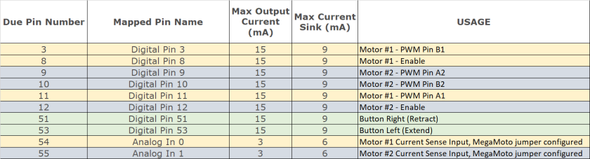
Arduino Due I/O Pin Assignment:
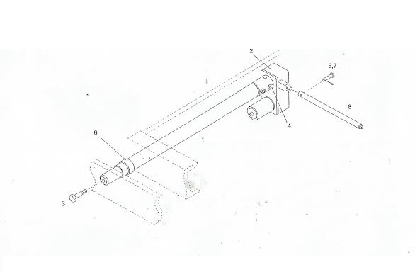
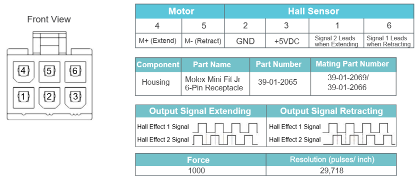
The Hall Effect Actuator I/O
The MegaMoto High-Current Motor Drivers
The MegaMoto is an implementation of Infineon H-Bridge Bi-directional Motor Control in a full bridge configuration:

Ok, if that’s too much then following is a much simpler explanation of a full-bridge motor controller:
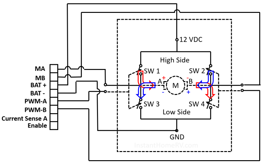
So the full bridge motor controller goes like this for the geekiness in you. Switches SW-1 and SW-3 are always opposite to each other. If SW-1 is open then SW-3 is closed, vice versa. Similarly, SW-2 and SW-4 are opposite to each other. Both sets are controlled by the MA and MB enable lines. The logic diagram is as follow:
| MA | MB | M+ | M- | Function |
| 0 | 0 | GND | GND | Motor Braking |
| 1 | 0 | 12 VDC | GND | Motor Forward |
| 0 | 1 | GND | 12 VDC | Motor Reverse |
| 1 | 1 | 12 VDC | 12 VDC | Motor Braking |
So our wiring diagram becomes like this. Each full bridge will drive one actuator motor and monitoring the positional feedback (Hall Effect feedback, more on this later):
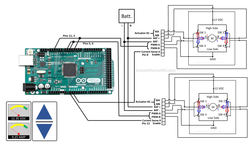
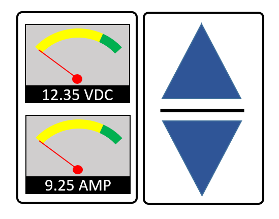
So now the only missing piece is the Human Machine Interface. So, this nifty little display concept will do the job just fine. The Up Arrow is for extend the slide-out command , the Down Arrow is for the retract the slide-out command. The two analog gauges shows the voltage and current of the slide-out actuators. Since there are two actuators per slide-out, the voltage is common for both, however, the current is different for each actuator, so the current gauge will alternate between actuator # and actuator #2 using different color text.
It’s been a long time I haven’t coded graphics so let see how it will turn out. I haven’t decided which display I will select for final design so I coded the programs for both displays. You can see the results from both later.
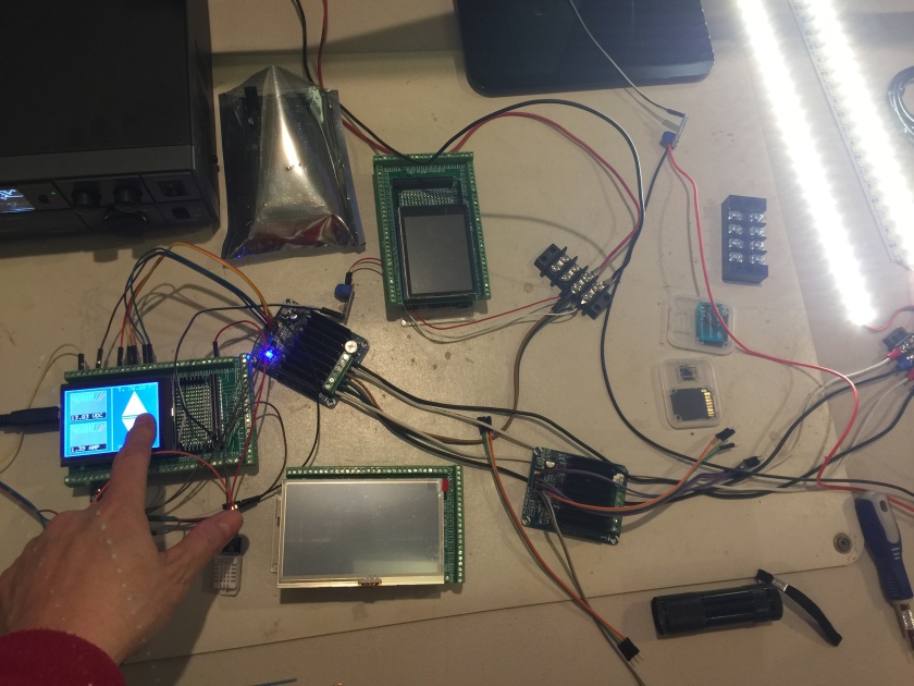
Ok, here’s the initial snapshot.
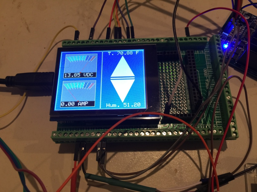
I also added in the humidity and temperature sensors. The temperature seemed to be accurate but the humidity was a disappointment. At least, the HMI looks decent.
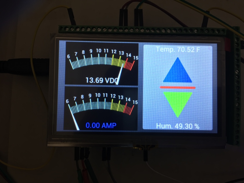
Here’s the same HMI with a much larger 4.3″ display. The codes are a bit more complex since this display comes with its own graphics engine. The menu display the common 12 VDC supply voltage of the actuator motors and the current gauge display the current drawn from each motor. The current gauge switches between the motor #1 and #2 every few seconds.
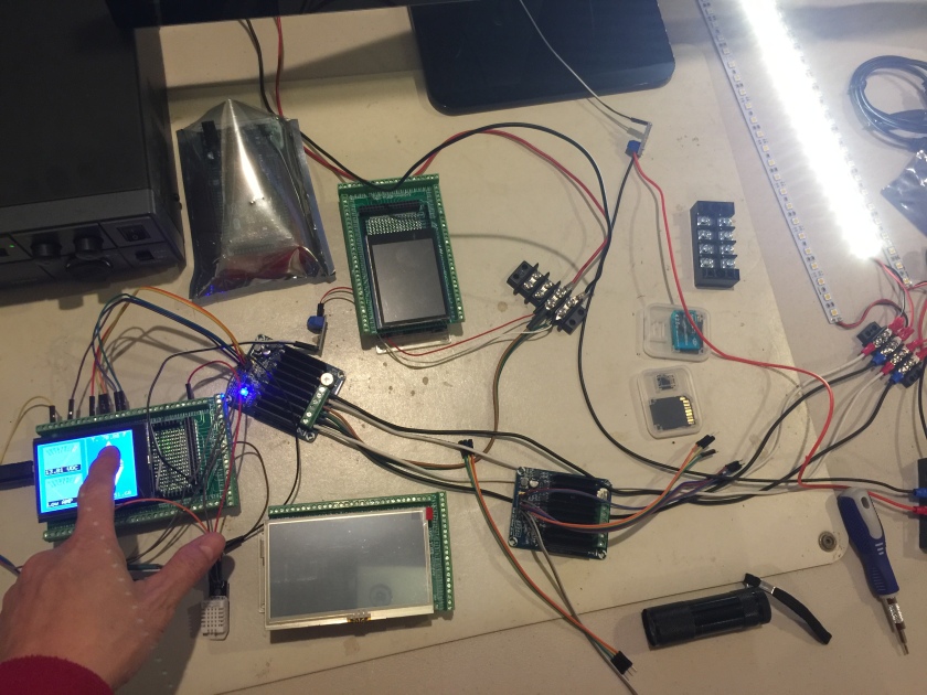
Since I don’t have the actuators ready yet. I wired the output of the H-Bridge to drive the LED lights. The light sets make a good test vehicle. These are 12 VDC LED and the touch buttons seems to work as intended.
Do I hear the UPS man at the door? May be that’s my actuator delivery. I can’t wait to test them out.
See you in a little while…or whenever I have a little bit of time to continue this project.
